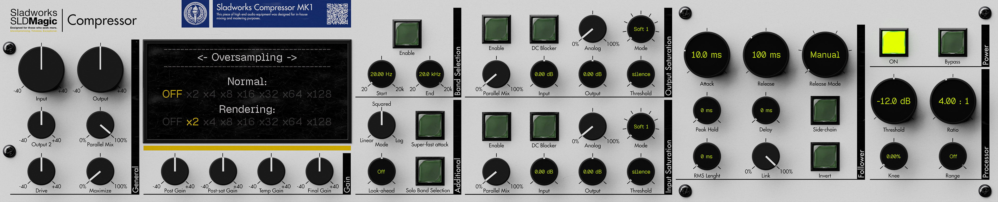
Sladworks Compressor MK1 is a proprietary dynamics processor interface built around the deep engine of MeldaProduction MTurboComp, reinterpreted through the Sladworks SLDMagic design doctrine. It is not designed as a simplified “one-knob” compressor. Instead, it presents compression as a visible, tunable system: detection, gain computation, saturation, level management, oversampling, and parallel control.
The MK1 reduces MTurboComp’s wider modular architecture into a focused compressor layout. Rather than exposing every available follower, processor, EQ, and internal module, it concentrates the design around one main follower, one main processor, dual saturation stages, precise gain staging, band selection, and render-quality control. The result is not a watered-down version of MTurboComp, but a curated machine built for direct operation.
The interface is intentionally dense. Its purpose is to keep the important parts of the compressor visible without turning the workflow into a raw edit-screen environment. Attack, release, RMS behavior, peak hold, side-chain response, ratio, knee, range, saturation, oversampling, drive, and parallel mix are all placed on the front panel because they directly shape how the compressor listens, reacts, and returns level.
Visually, the MK1 borrows from high-end digital hardware, mastering processors, laboratory instruments, and rack-mounted technical equipment. It does not imitate a specific vintage compressor. Instead, it uses physical depth, sectional layout, LCD-style precision readouts, switches, screws, labels, and a rendered front panel to make the interface feel like a serious operational instrument.
Functionally, the Sladworks Compressor MK1 sits between a mixing compressor, tone-shaping compressor, and mastering-oriented dynamics tool. It can be used lightly for transparent control, driven harder for saturation and density, or pushed into higher-quality processing through oversampling and render-mode settings.
Documentation
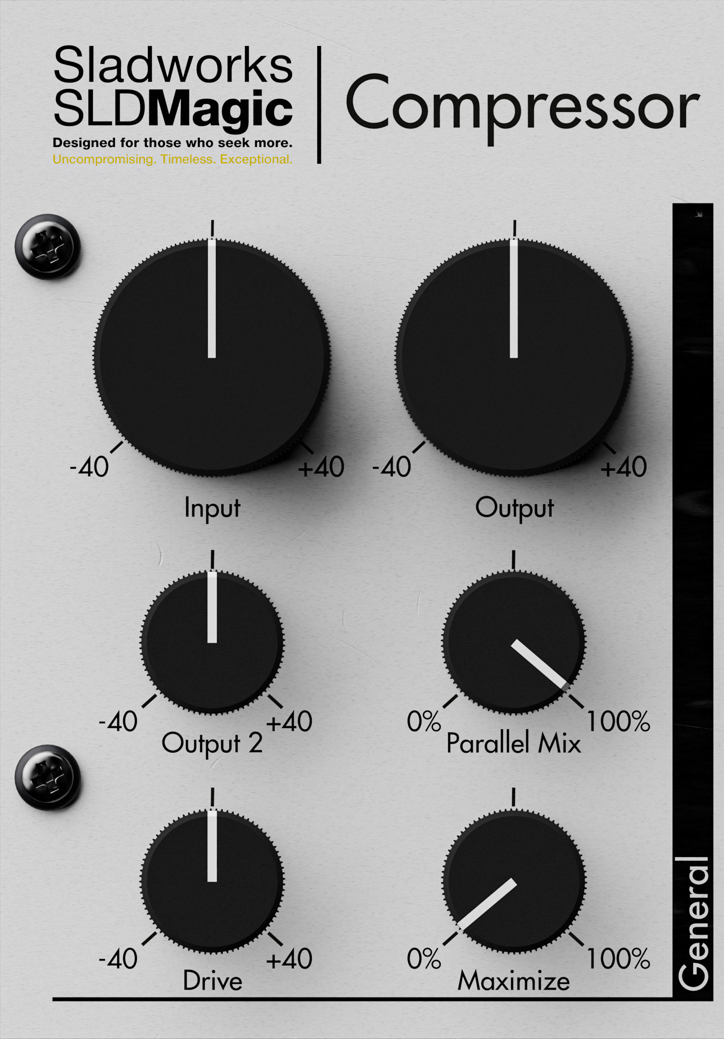
The General section controls the broad gain structure of the Sladworks Compressor. It contains the main input and output stages, along with additional level, drive, blend, and maximization controls for shaping how strongly the processor is driven and how much of the processed signal is returned.
Input applies gain at the very beginning of the signal path. Since it affects the signal before detection, changing this control can also change how the compressor reacts.
Output sets the main output level after processing. Output 2 provides an additional output gain stage, included for workflow convenience and easier device layout.
Drive applies gain before the follower section. Unlike the main input gain, this stage is part of the processed path and is affected by the parallel mix behavior, making it useful for pushing the compressor harder without treating it purely as global input trim.
Parallel Mix controls the balance between dry and processed signal. At 100%, the signal is fully processed; at 0%, the original signal passes through unchanged. This allows parallel compression directly from the front panel, making it possible to use heavier compression while blending it back into the dry signal.
Maximize applies automatic output compensation based on the current processing shape. It is intended as a fast way to recover level after compression without manually balancing every gain stage.
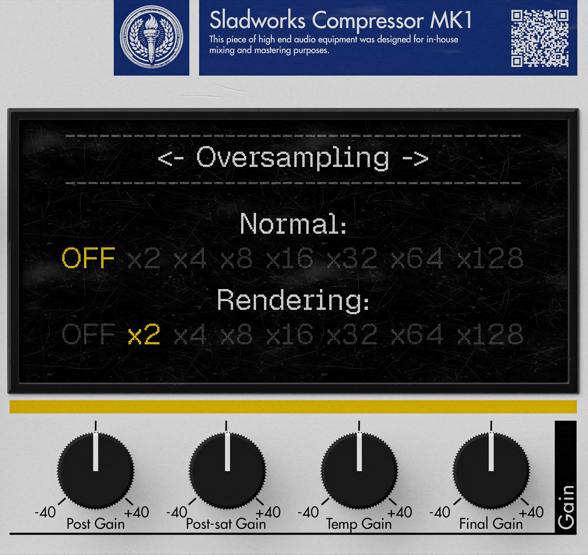
The Gain section continues the compressor’s level-management structure with additional gain stages placed at different points in the internal signal path. These controls are separated from the main General section to make the gain architecture easier to read and adjust.
Post Gain changes the processed level without affecting the follower section. Unlike Input gain, it does not change how the detector reacts, which makes it useful for level balancing after the compressor behavior has already been established.
Post-sat Gain adjusts the level after the saturation stages and before the parallel mix stage. It is useful for balancing the signal after harmonic drive has been added.
Temp Gain temporarily raises or lowers the input level and then compensates for that change later in the path. In practice, it can act as a compression-intensity control: increasing it pushes the signal harder into the threshold while aiming to keep the output level more stable.
Final Gain is the last gain stage in the device. It is applied after the parallel mix and works as the final output trim before the signal leaves the compressor.
The display area above this section gives access to system-level pages such as oversampling. In the shown page, Normal controls the real-time oversampling setting, while Rendering controls the oversampling used during offline export or render. This allows the compressor to run lighter during active work while reserving higher processing quality for final output.
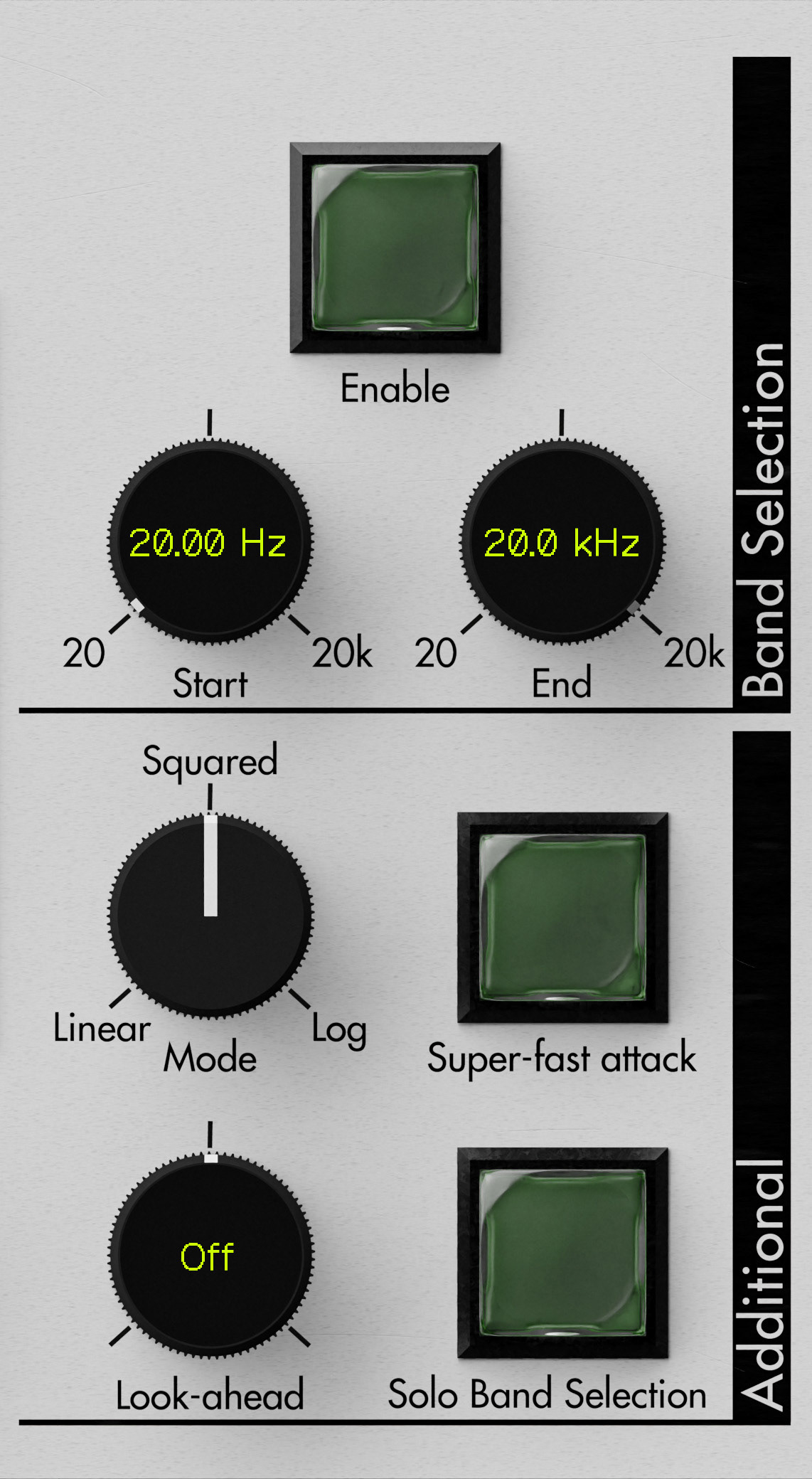
The Band Selection section limits the range of signal used for detection and processing control. Start and End define the active frequency window, from low frequencies up to the top of the audible range. This makes it possible to focus the compressor’s behavior on a selected part of the spectrum instead of letting the full signal trigger the processor equally.
Enable activates the band selection stage, while Solo Band Selection allows the selected band to be monitored directly. This is useful when setting the frequency boundaries by ear, especially when targeting low-end movement, vocal presence, harshness, or other specific areas of the signal.
The Additional section contains behavior controls that change how the processor reacts.
Mode changes the processing shape. Log gives the most classic compression behavior, while Squared and Linear progressively increase the amount of compression or expansion for the same threshold and ratio relationship. These modes do not represent quality levels; they are different transfer shapes.
Look-ahead allows the detector to react before the processed signal arrives by delaying the audio path while keeping detection forward in time. This can make the compressor react faster and cleaner, especially for limiting-style behavior, but it also introduces latency and can create artifacts if attack, release, and hold behavior are not balanced carefully.
Super-fast attack forces the processor to react as quickly as possible so the level does not pass the threshold in the usual way. It is designed specifically for compression behavior and is not intended for gating or downward-style processing.
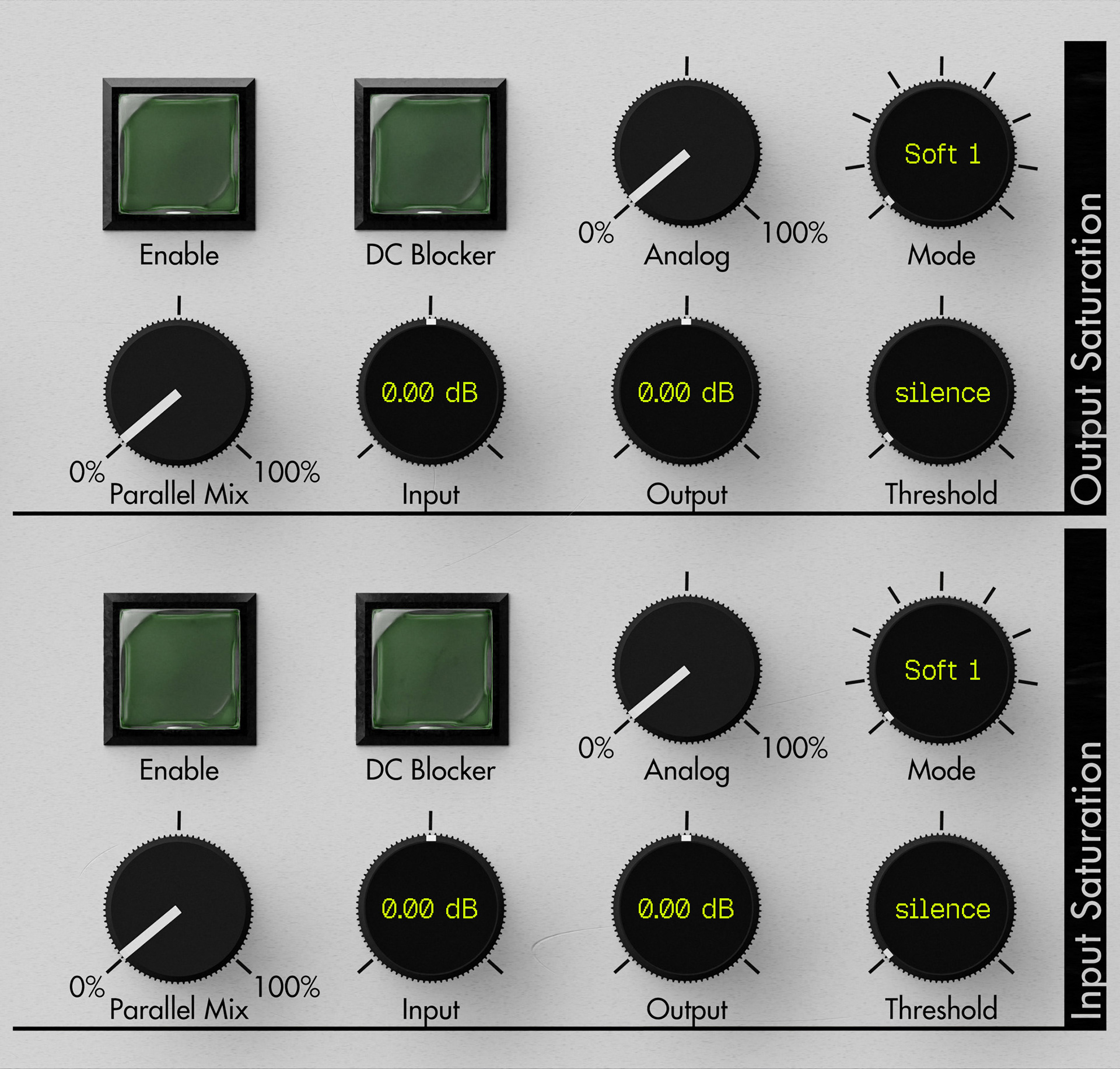
The Saturation sections control the harmonic coloration stages of the compressor. The layout is split into Input Saturation and Output Saturation, allowing saturation to be applied at different points in the signal path.
Enable activates the saturation unit for the selected stage.
DC Blocker activates an integrated DC offset filter. This is useful because harmonic processing can introduce unwanted signal offset.
Parallel Mix controls the blend between the dry and saturated signal. At 100%, the saturation stage is fully blended in; at 0%, none of the saturated signal is added.
Input sets the gain feeding the saturator. Increasing it drives the saturation stage harder and produces more harmonic coloration.
Output sets the gain after the saturation stage. It is used to compensate the level after added drive or coloration.
Threshold defines the minimum signal level above which the saturation begins to act. Lowering the threshold makes the saturation engage more easily, increasing loudness and distortion.
Analog controls the amount of even-harmonic character added alongside the main saturation. The amount follows the saturation behavior itself, rather than acting as a completely independent harmonic generator.
Mode selects the saturation shape and character. In this interface, the mode control is exposed as a precision readout because the selected curve directly changes the tonal behavior of the stage.
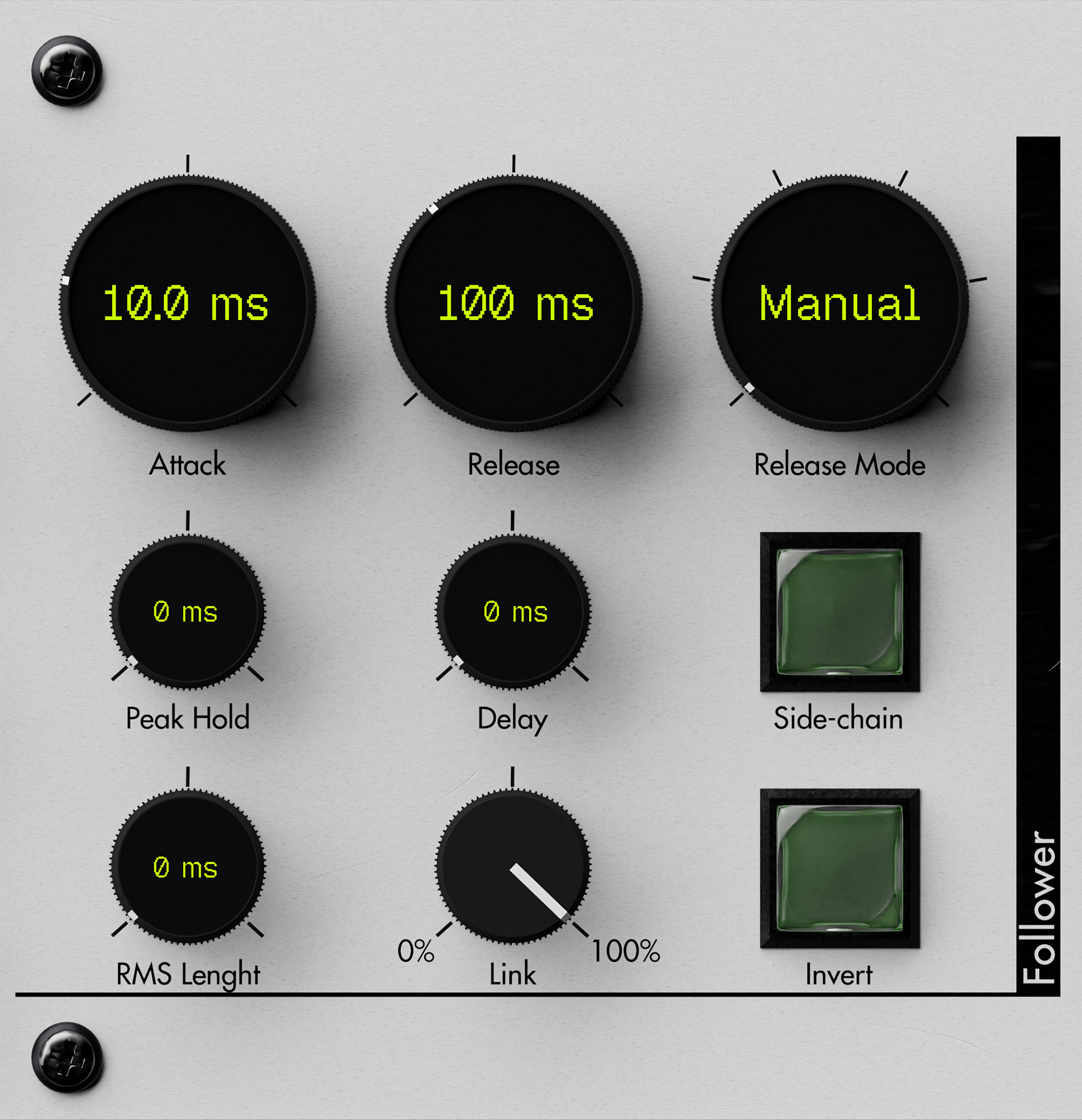
The Follower section defines how the compressor measures the incoming signal before applying dynamics processing. It controls the behavior of the level detector: how quickly it rises, how quickly it falls, how smooth or peak-sensitive it is, and how stereo channels or side-chain signals influence the detector.
Attack sets how quickly the detector rises when the input level increases. Shorter attack values make the compressor react faster to transients, while longer values allow more of the initial hit to pass before compression takes over.
Release controls how quickly the detector falls when the input level decreases. Short release times let the compression recover quickly, while longer release times keep the processing active for longer and can create a more stable, controlled response.
Release Mode changes the way release behavior is calculated. Manual uses the release time directly, while automatic modes can adapt the release response depending on the signal’s level or duration.
Peak Hold keeps the detected level at its maximum for a set amount of time before release begins. This is useful for preventing the detector from dropping too quickly and can also work together with look-ahead for cleaner limiting-style behavior.
RMS Length smooths the detected level before it reaches the attack/release stage. At minimum, the follower behaves like a peak detector; higher values create a smoother RMS-style response. This can make compression more stable, especially for mastering or broad level control, but it reacts more slowly to sharp transients.
Delay delays the follower output itself. This can be used to preserve attacks or to create more complex detector behavior when combined with other timing controls.
Link controls how much the channels influence each other. At 0%, each channel is detected independently. At 100%, the channels are linked so the processor applies more unified gain reduction across the stereo image.
Side-chain uses the side-chain input as the detector source instead of the main input signal.
Invert flips the detected envelope behavior, turning the follower output from normal to inverted response. This is mainly useful for creative or more experimental dynamics behavior
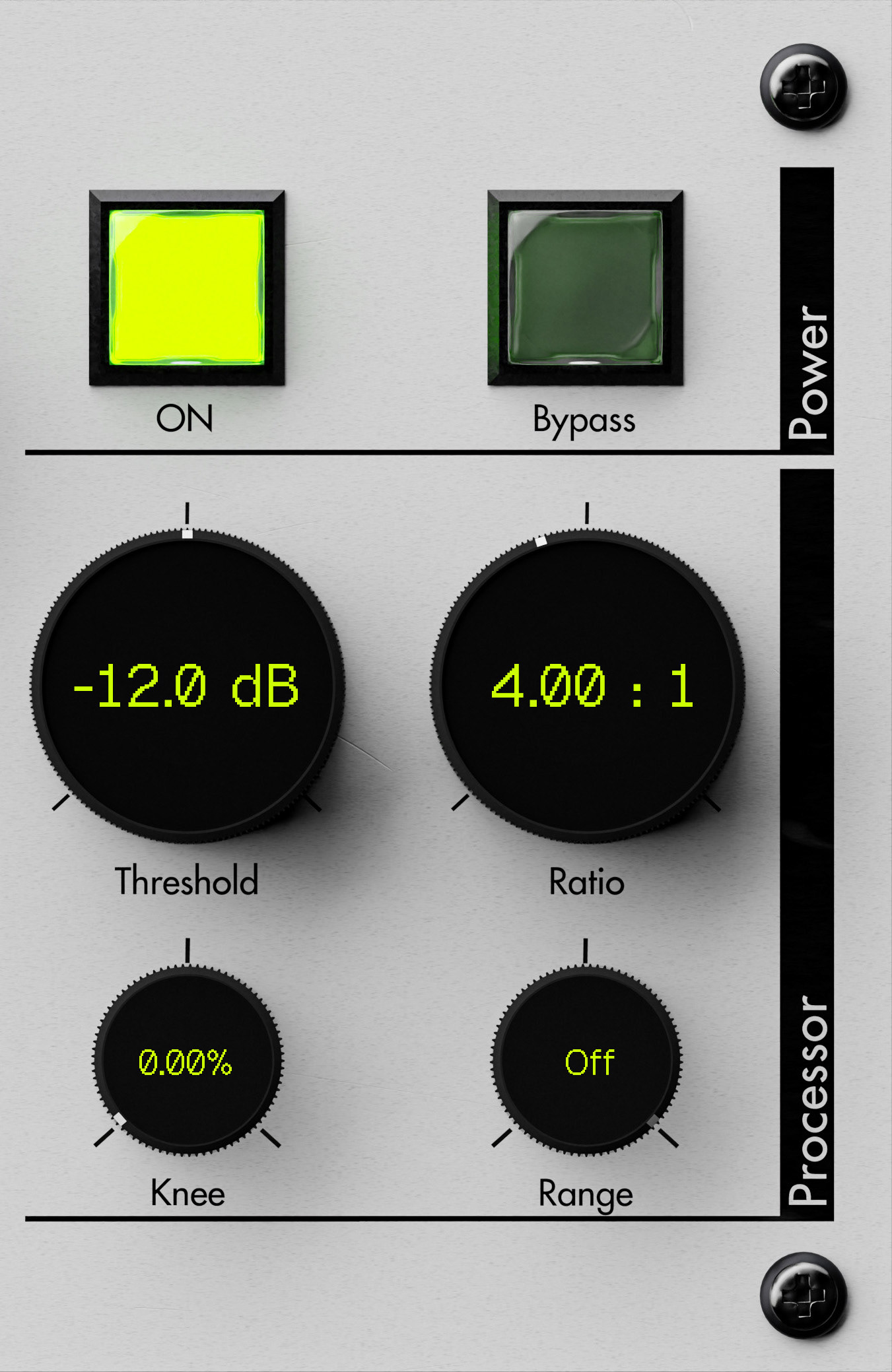
The Power section contains the main state controls for the device. ON activates the compressor, while Bypass allows the processor to be taken out of the signal path without changing the current settings.
The Processor section defines the main compression curve. This is where the core dynamic behavior is set: when compression begins, how strongly it reacts, how smoothly it enters processing, and whether the effect is limited to a specific range above the threshold.
Threshold sets the signal level above which compression begins. Signals below this point pass without triggering the main compression behavior, while signals above it are processed according to the ratio and curve settings.
Ratio controls the strength of compression above the threshold. Higher ratios apply more gain reduction, while lower ratios produce gentler dynamic control.
Knee smooths the transition into compression. At 0%, the processor enters compression sharply once the threshold is crossed. Higher values create a softer curve, making the compression more gradual and less obvious.
Range limits how far above the threshold the compression curve remains active before the original signal ratio is restored. When set to Off, this limiting behavior is disabled and the processor follows the normal compression curve.
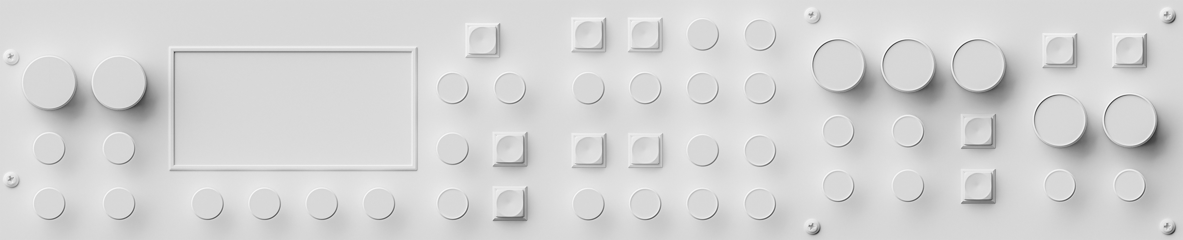
To present the form without the distraction of labels, color, or emissive elements, the interface is also shown as a material-override clay render. This view highlights the raw 3D construction of the front panel: proportions, control spacing, bevel definition, and surface depth. Rendered in Blender Cycles, it demonstrates that the interface is not a flat mockup but a fully built three-dimensional object, lit and shaded with physically realistic detail.